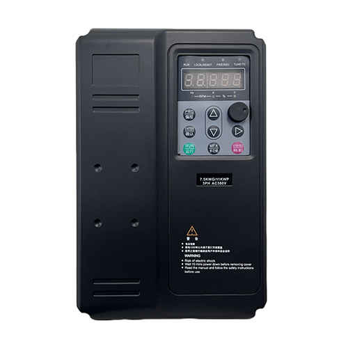
Here are the diagnosis and treatment of common faults of frequencyinverters
Whether the commonly used frequencyinverters can meet the requirements of the transmission system during use, the parameter settings of the frequencyinverter are very important. If the parameter settings are incorrect, the frequencyinverter will not work properly.
Once a parameter setting fault occurs, thefrequencyinverter cannot operate normally. Generally, the parameters can be modified according to the instruction manual. Ifit does not work,we should restore all parameters to factory values, and then reset according to the above steps. The parameter restoration methodshould be taken according to different company'smachine.
The overvoltage of the frequencyinverter is concentrated on the tributary voltage of the DC bus. Under normal circumstances, the DC power of the frequencyinverter is the average value after three-phase full-wave rectification. If calculated based on 380V line voltage, the average DC voltage Ud= 1.35 U line=513V. When overvoltage occurs, the energy storage capacitor of the DC bus will be charged. When the voltage reaches about 760V, the inverter overvoltage protection will operate. Therefore, the frequencyinverter has a normal operating voltage range. When the voltage exceeds this range, it is likely to damage the frequencyinverter. There are two common types of overvoltage:
2.1 The input AC power supply is overvoltage, which means that the input voltage exceeds the normal range. It usually occurs during holidays when the load is light, the voltage increases or decreases and the line fails. At this time,we should disconnect the power supply, check and deal withthe faults.
2.2 Power generation overvoltage,which has a high frequency. The main reason is that the synchronous speed of the motor is higher than the actual speed, causing the motor to be in a power generation state, and thefrequencyinverter is not equipped with a braking unit. There are two situations that can cause this fault.
(1) When the frequencyinverter drives a large inertia load, its deceleration time is set relatively small. During the deceleration process, the frequencyinverter outputs a faster speed, while the load decelerates slowly due to its own resistance, causing the load to drive the motor at a faster speed. The speed is higher than the speed corresponding to the frequency output by the inverter. The motor is in a power generation state, and thefrequencyinverter does not have an energy feedback unit. Therefore, the voltage of the tributary DC circuit of themachine rises, exceeds the protection value, and a fault occurs. Dealing with this fault can increaseregenerative braking unit, or modify the parameters to seta longer deceleration timeof the machine.
(2) This fault may also occur when multiple electric motors operate the same load, mainly due to the lack of load distribution (its primary and secondary distribution problems).
Take two motors dragging a load as an example. When the actual speed of one motor is greater than the synchronous speed of the other motor, the motor with a high speed is equivalent to the prime mover, and the one with a low speed is in a power generation state, causing a fault. In this machine, it often occurs in the press section and net section, and load distribution control is required during processing. The characteristics of the frequency converter at the branch of the paper machine transmission speed chain can be adjusted to be softer.
Overcurrent faults can be divided into acceleration, deceleration, and constant speed overcurrent. Acceleration and deceleration overcurrent is caused by theshort time setting of the frequencyinverter's acceleration and deceleration, load mutation, uneven load distribution, output short circuit, etc. At this time, it is generally possible to extend the acceleration and deceleration time, reduce sudden changes in load, add energy-consuming braking components, carry out load distribution design, and inspect the line. If the overcurrent fault persists after disconnecting the loadfrequencyinverter, it means that the inverter circuit has gone into a loop and themachine needs to be replaced.
Frequencyinverter overload includes its own overload and motor overload. The overload of the frequencyinverter is caused by the acceleration and deceleration time being too short (forming a short-term overload) and the DC braking amount being too large. Maintenance: Extend the braking time by changing its internal parameters. Motor overload is caused by reasons such as too low grid voltage and overload. Maintenance: Check the power grid and voltage. The load is too heavy. The selected motor and frequencyinverter cannot drag the load. It may also be caused by poor mechanical lubrication (excessive resistance).
(1) Undervoltage. It means there is a problem with the power input part of the inverter and it needs to be checked before it can be run.
(2)Hightemperature. If the motor has a temperature detection device, check the heat dissipation of the motor; if the temperature of thefrequencyinverter is too high, check the ventilation of themachine.
(1) The motor cannot start.
Main circuit inspection: power supply voltage detection, whether the charging indicator light is on, whether the LCD displays an alarm screen, and whether the connection between the motor and the inverter is correct.
Input signal check: whether the start signal and FWD and REV signals are input, whether the frequency has been set or the upper limit frequency is too low.
Function setting check: Whether the various function code settings are correct.
Load check: Whether the load is too large or the machine is blocked.
(2) The speed of the motor cannot be adjusted.
It may be because the upper and lower frequency limit settings are incorrect, or the timing setting value is too long when the program is running. When the maximum frequency is set too low, a fault in which the frequency cannot be adjusted may occur.
(3) The motor stalls during acceleration. It may be caused by the acceleration setting time being too short or the load being too large and the torque boost not being enough.
(4) The motor is abnormally hot. Check whether the load is too large, whether it is running at low speed continuously, and whether the set torque increase is appropriate. If it does not fall into these reasons, it may be that the three-phase output voltage (UVW) of the inverter is unbalanced.


 中文(简体)
 English
 日本語
日本語 한국인
한국인 Deutsch
 español
 Português
 Français
 Tiếng Việt
 italiano
 Русский
 عربي
عربي